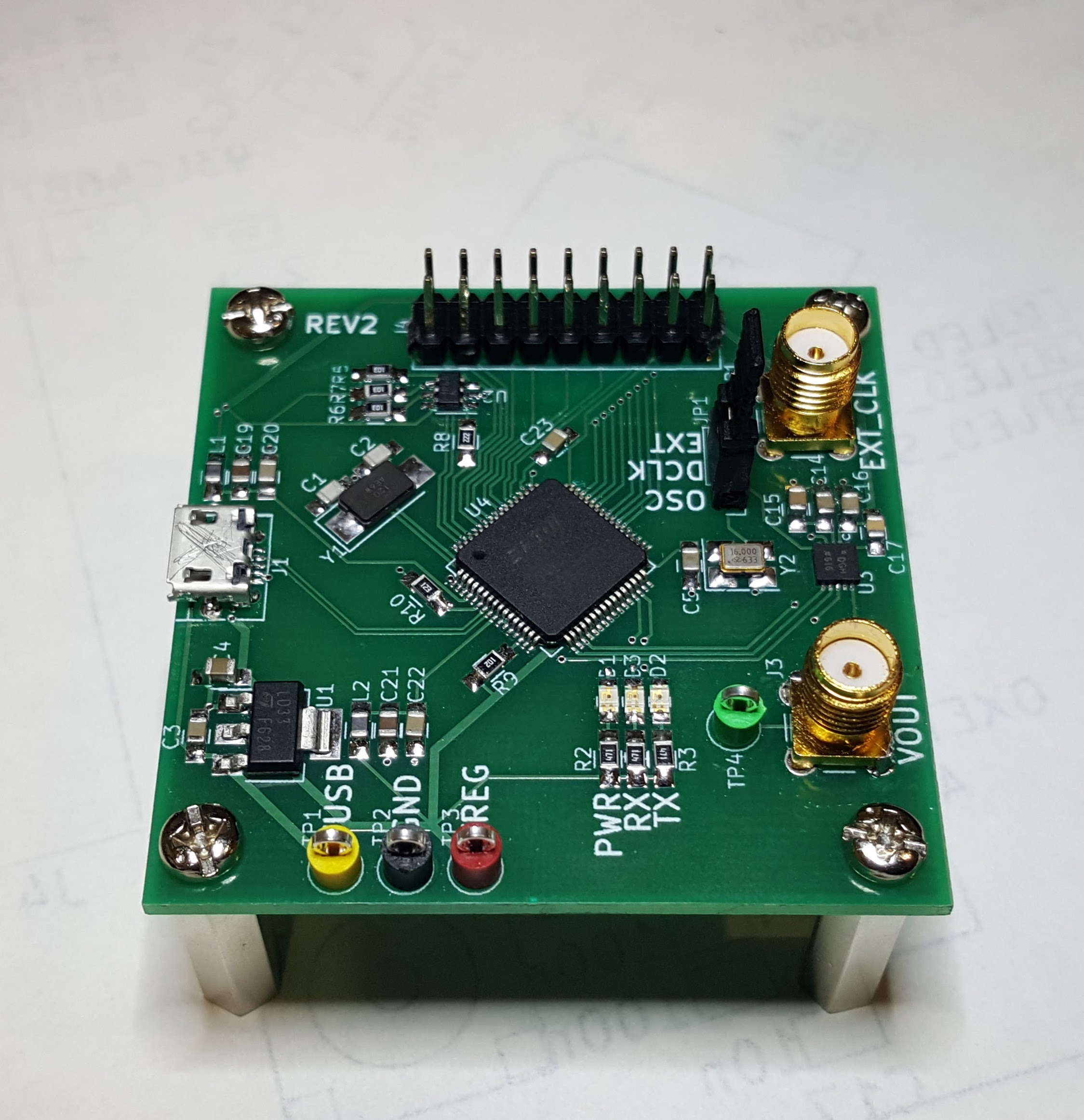
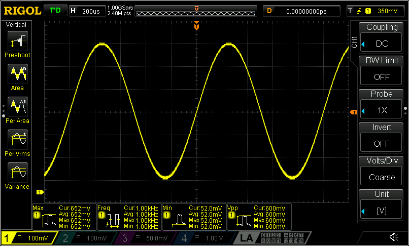
This is an implementation of a USB-controlled Analog Devices AD9837-based function generator that can generate sine, triangle and square waves up to around 200 kHz or so, 1 MHz if the output filtering capacitor is removed (although the quantization of the ADC starts to become apparent around 500 kHz).
There are several off-board connectors, one jumper and three LEDs.
| Reference | Purpose |
|---|---|
| J1 | Micro-B USB Connector |
| J2 | External clock input |
| J3 | Function generator output (0.6Vpp typical) |
| J4 | FTDI channel B breakout |
| TP1 | USB supply voltage (5V typical, 15V max) |
| TP2 | GND |
| TP3 | LD1117 output (3.3V nominal) |
| TP4 | Function generator output (0.6Vpp typical |
| JP1 | Clock select jumper |
| D1 | LD1117 power indicator |
| D2 | Currently unused |
| D3 | Currently unused |
At some point I'll document the pinout for the J4 connector here. Until then the pinout is available in the schematic.
Indicators D2 and D3 were originally intended as SPI TX/RX indicators, but that was before I realized that the FT2232H only enables them for UART communication (and also that the AD 9837 has no TX...). There's nothing stopping the control software from using them for other purposes, although the silkscreen on rev. 2 would be misleading.
Because the design is based on the FTDI FT2232H, there's no firmware per se.
However, the control software looks for certain USB product and manufacturer
strings to differentiate the device from other FTDI devices. A template for
the FTDI 'FT_Prog' EEPROM programming software is provided in the firmware/
directory. The device should be programmed with this template before attempting
to use the control software.
The control software is a work in progress, but the device can currently be fully controlled via a provided software library. The library is written in C++ and requires a compiler with C++11 support.
To build the library, you will need CMake and a suitable C++ compiler. On linux, the build steps go something like this:
$ sudo apt-get install git build-essential cmake libftdi-dev
...
$ git clone [email protected]:Fifty-Nine/wavegen
...
$ cd wavegen/software
$ mkdir build
$ cd build
$ cmake ..
...
$ make
...
$ sudo make install
...
$
At this point, you can use the wavegen-test program to confirm that the device
is working. The test program initializes the device and repeatedly performs a
frequency sweep.
A GUI control interface would be nice to have.
One major limitation of the current hardware is that it provides no output amplitude control or amplification. At some point I would like to design an amplification stage with automatic gain control. Rev 3 will allow arbitrary waveform generation, so this will be mitigated somewhat.

