-
Notifications
You must be signed in to change notification settings - Fork 3
1.1 Software Development Methodology
In order to create a high quality and robust end product, we used the well-tested waterfall software design process.
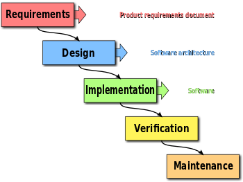
The waterfall model is a heavyweight process that is primarily linear and follows well defined stages that must be completed in order. These stages are requirements gathering, design, implementation, verification and maintenance. For this project, maintenance is not yet applicable, but for future use of the project, it will be. These phase and displayed in the following diagram:
This process involved three major stages throughout the development of the Kiwifruit orchard robot simulator as detailed below:
- First was the gathering of the user and client requirements. This included clarifying what features the client wanted in the Kiwifruit orchard robot simulator and how they wanted it to be implemented. We collected this information through the project brief as well as asking questions on the forum and asking the clients face to face. This is arguably the most important phase of the design process, as ultimately as software developers we were tasked to create a product for a client, and therefore the main goal of this design project was to make the product as close to what the client wanted as possible. This meant that we had to ensure that all the client requirements were satisfied to the client’s specification, ensuring fitness for purpose.
Once requirements were carefully ascertained, modelling processes were used to synthesize the requirements into tangible substructures:
-
Once requirements were collected, modelling processes were used extensively to create a high-level design. To ensure high quality software, detailed modelling is essential. This is why we decided to take a user-centric view on the project by designing top-down. Designing top down meant focusing on exactly how the application should look like and how the user interacts with it. We used UML class diagram modelling to help determine the class structure of our main program, to break down the different subtasks into discrete sections that each team member could work on independently, which could later be integrated into a complete working system.
-
Lastly, once the concepts were modelled, we began designing in actual code, taking careful note of anything that needed to be clarified with team during bi-weekly meetings. Once a specific feature was completed, it was tested and then merged back into the master branch so that everyone could always work with the latest changes generated from other team members.
-
Once every section was integrated successfully, they were verified against the specifications and requirements to ensure fitness for purpose. Any features that were missing or did not adhere to the brief would subsequently be worked on until the requirements were met.
##1.0 Introduction
##2.0 User Manual
##2.5 Testing
3.1 Launch Infrastructure
3.2 Entities and behaviours (Robots, humans, animals)
- 3.2.1 Entity Superclass
- 3.2.1.1 Entity Movement
- 3.2.2 Robot Entity
- 3.2.2.1 Robot Entity Detection
- 3.2.2.2 Robot Path Finding
- 3.2.3 Robot Pickers
- 3.2.4 Robot Carriers
- 3.2.4.1 Carrier Queue
- 3.2.5 Humans
- 3.2.6 Animals
- 3.2.7 Entity Topics
3.3 Special services and features
##4.0 Project Planning and management
- 4.1 Project plan
- 4.2 Git Branching and Merging Etiquette
- 4.3 Design Requirements, System requirements and Technical specifications
- 4.4 Key Factors and Constraints
- 4.5 System Design
- 4.6 Time spent
- 4.7 Testing and integration overview
- 4.8 Meeting minutes
##Miscellaneous resources
